
SolarEdge SE3800A-US Solar Inverter 3G to WiFi Ethernet Bridge
My SolarEdge inverter went offline. Here is the low-cost fix that brought it back.
A hands-on troubleshooting story: replacing an obsolete cellular modem with a compact Wi-Fi-to-Ethernet bridge, carefully powered from a verified 5 V rail.
My SolarEdge system was still generating power, but the monitoring app had gone silent. The dashboard said “Site not communicating,” showed 0 Wh for weeks, and left me with no way to tell whether my biggest energy asset was actually working. On solar, monitoring isn’t a nice-to-have — it’s how you know the system is performing.
I wanted a fix that was economical and certain: no recurring cellular dependency, no expensive replacement kit, and no long new Ethernet and power cord running through the outter wall. The answer was a compact Wi-Fi-to-Ethernet bridge that lets the inverter use the RJ45 LAN port it already has.
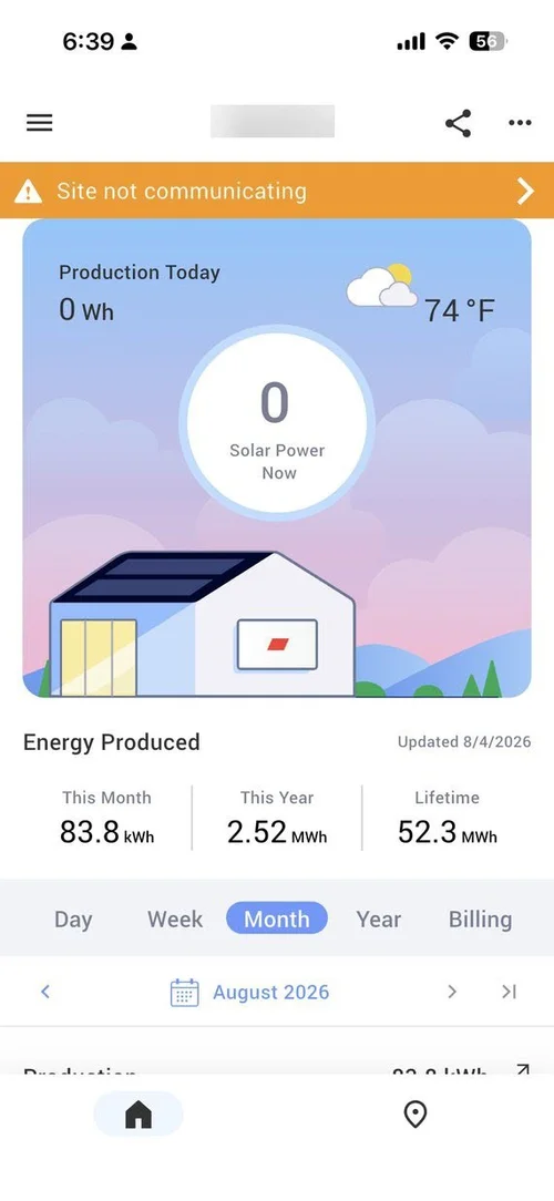
The real problem: communications, not necessarily production
An offline portal does not automatically mean a dead inverter. The first diagnostic habit worth building is separating two questions: Is the system producing? and Can the inverter reach the monitoring server? Answer them independently, and most SolarEdge “outages” stop being scary.
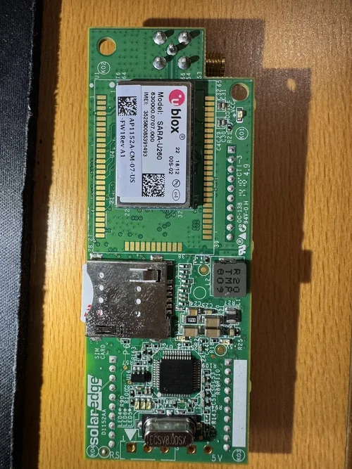
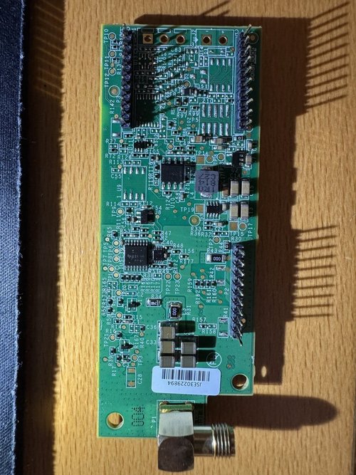
Inside my inverter sat an older cellular communications board built around a u-blox SARA-U260 — a 2G/3G-era modem. The US carriers finished retiring their legacy 3G networks between 2022 and 2024, so this wasn’t a glitch. It was a technology that had reached the end of its road. Honestly I was suprised it worked until mid 2026 in my neighborhood.
SolarEdge does sell a replacement 4G cellular kit, CELL-A-R05-US-S-S2. Community pricing discussions put it at roughly $450, including the modem, SIM, and an initial three years of cellular service. That is the right answer for some installations. I just didn’t want to re-enter the same carrier-dependent lifecycle in a few more years.



Choosing the practical path: LAN over Wi-Fi
The cleanest, most future-proof option is a direct Ethernet cable from the home router to the inverter. The inverter already has an RJ45 Ethernet port behind the display, and wired Ethernet ends the cellular-service question entirely.
For my layout, pulling a new cable across the house, through an outter wall would cost more effort than the problem deserved. Wi-Fi at the inverter location was solid, so I took the middle path: a small VONETS-style Wi-Fi bridge joins the household Wi-Fi and presents a plain wired Ethernet connection to the inverter.
| Approach | Why choose it | What to consider |
|---|---|---|
| New 4G cellular kit | Simple where Wi-Fi and Ethernet are impractical | Higher upfront cost and a carrier/service lifecycle |
| Dedicated Ethernet run | Most robust and least dependent on wireless signal | May require routing, conduit, wall penetration, or labor |
| Wi-Fi-to-Ethernet bridge | Low cost; inverter sees a wired LAN connection | Needs strong Wi-Fi and careful low-voltage installation |
Why this worked: the bridge handles the Wi-Fi. To the inverter, it is simply an Ethernet cable plugged into its LAN port. That avoids the retired cellular pathway without a long Ethernet pull.
The important part: prove the 5V and ground pins first
The networking decision was the easy part. Powering the bridge safely is where the job actually lived. The bridge needs 5 Volts, and the old communications-board connector looked like it could supply it — but no pinout diagram was published, and I wasn't able to get detailed help online.
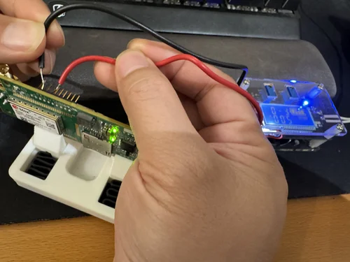
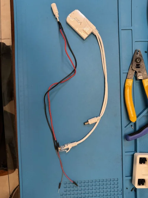
Thus, I shut the inverter down per its documented procedure, pulled out the 3G cellular board, then used a multimeter to identify ground and +5 V on the actual board, verified continuity against a known reference, confirmed the intended contacts with a known power source, and bench-tested the bridge before anything went near the enclosure.
- Shut the inverter down according to its documented procedure before accessing electronics.
- Identify ground and the +5 V rail on your specific connector and board revision.
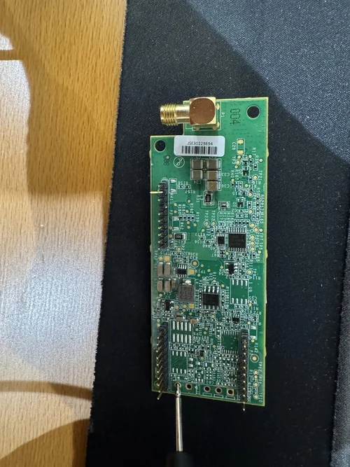

- Check continuity to a known reference at the bottom of the card where it says 5V +, -; do not rely on an assumed connector pinout.
- Confirm polarity and voltage before connecting the bridge.
- Bench-test the custom lead and bridge before final installation.
- Insulate and strain-relieve all low-voltage wiring; keep it away from high-energy conductors and sharp edges.


Installation: Ethernet, weather sealing, and cable management
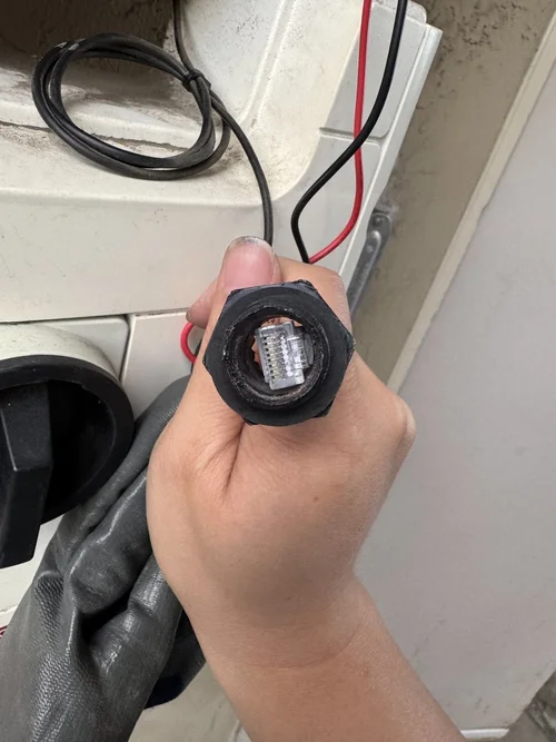
With the bridge configured for the home Wi-Fi and its power lead verified, I connected the bridge’s Ethernet output to the inverter’s existing Ethernet port and routed the Ethernet and low-voltage wires through the enclosure entry area.
But first, do a quick power on test, make sure it all works before running the wires properly.
Then go into setting mode, by pressing and holding the only button available on the enclosure for about 5 seconds(single press to scroll, press and hold to select). Then navigate through the menu to where it says "server", change server selection from Cellular to Ethernet.

The existing bushing was slightly too small for the connection path, so it needed careful enlargement by a hand drill. A cable route has to remain protected from sharp edges, water ingress, dust, and strain — a working network bridge is not a success if it compromises the inverter enclosure.

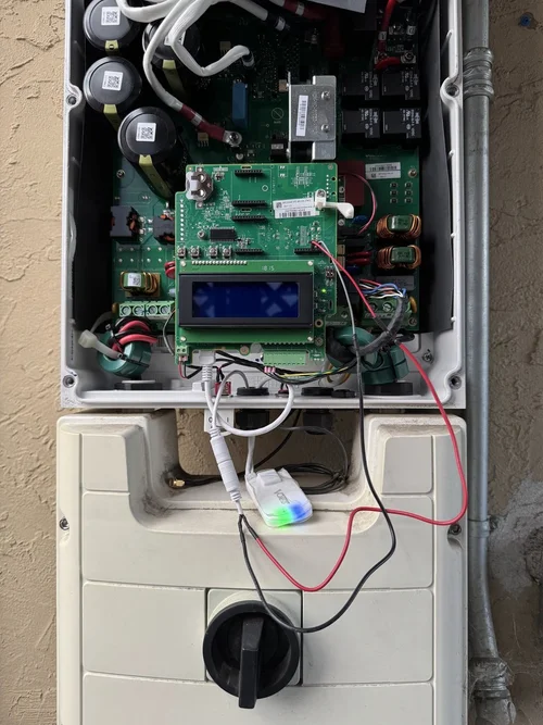
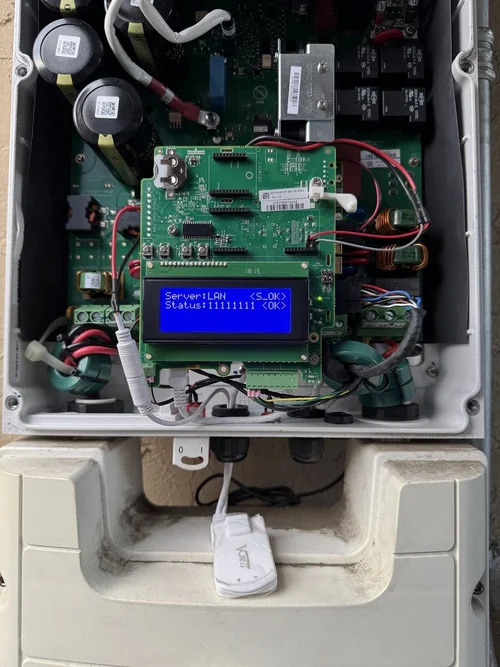
I added a small protective enclosure for the bridge, (as it is not weather prof at all, and has visible gaps in its enclosure) and did a final visual check before closing everything up: no loose leads, no pinched cables, and no compromised seal.
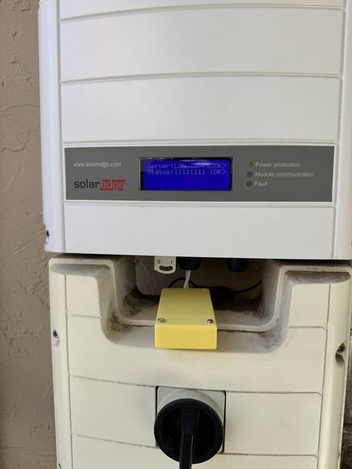
The proof: Server: LAN <S_OK>
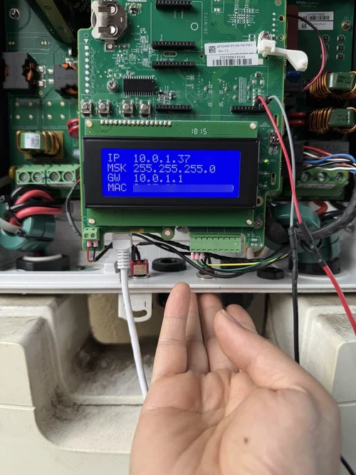
The inverter display first picked up a LAN IP address. Then came the line that mattered:
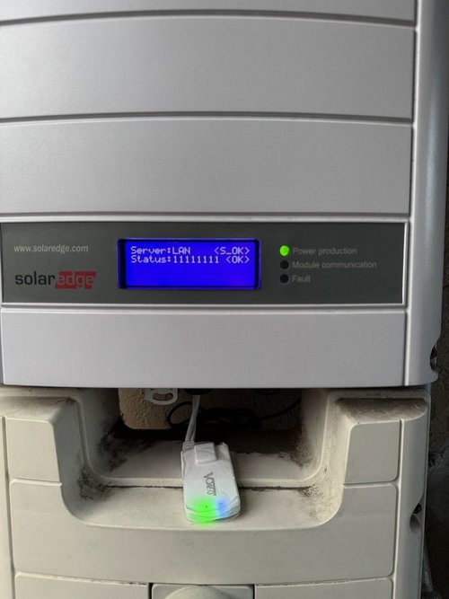
Server: LAN <S_OK> means the inverter reached the SolarEdge monitoring server over the local network and completed the connection. No cellular module, no carrier, no subscription — just a working LAN link.

Monitoring returned—and so did the missing data
Once the connection was restored, the mySolarEdge app caught up fast — backfilling at least two weeks of historical production data. At the post-repair capture, the dashboard showed 531 kWh for the month, 2.97 MWh for the year, and 52.7 MWh lifetime. The system had been producing the whole time; I just couldn’t see it.

To be honest, the bridge was the easy part. The real win was finally being able to see that my system was producing — and trusting it again. When you can't see what your equipment is doing, every decision is a guess. ChargeXcel removes that guess for EV charging: a UL 916-certified EV energy management system that shows your home's real-time electrical usage and manages EV charging within it, so qualifying homes get fast Level 2 charging without a panel or service upgrade.
What I would tell other SolarEdge owners
If monitoring has stopped, start by separating production from communications. Then choose the connection path that fits your property and your risk tolerance:
- Check the inverter and app status before assuming the solar system itself has failed.
- If practical, run dedicated Ethernet—it remains the most robust option.
- If Ethernet is impractical but Wi-Fi is strong, a quality Wi-Fi-to-Ethernet bridge can be a cost-effective alternative.
- Do not modify inverter power wiring unless you can safely identify and verify every connection on your exact hardware.
- Verify the inverter gets an IP address and displays a successful LAN/server status before closing the enclosure.
This project restored monitoring without a costly cellular replacement and without a long network run. More importantly, it put the system back on a connection method I can understand, test, and maintain — which, for a homeowner, is the whole point.
Know your energy. Charge smarter.
Restoring solar monitoring gave back the information needed to make better decisions about home energy use. ChargeXcel does the same for EV charging — helping homeowners and installers plan practical charging and load-management solutions around real electrical constraints, without guesswork or unnecessary upgrades.
Explore ChargeXcel solutions →